Monthly Archives : June 2017

My Perfect Green Data Centre (7) – Photovoltaics

Back to engineering, but first a disclaimer. Whatever numbers I use in this post are wrong. Photovoltaic technology (solar panels) and battery technologies are evolving so rapidly that everything is out of date as soon as it hits the market. So although I believe myself to have got the concepts right, the calculations are intended to show the type of calculation involved, but probably over-estimate the downside and under-estimate the upside. Having said that, the numbers are not order-of-magnitude wrong. They may be 10% or 20% out, but probably not much more.

The advantages of using solar are obvious: sunlight is – at least until the oil companies get their hands on it – free. Photovoltaic (PV) panels generate DC, not AC, and most of our load is DC. That’s a single conversion from photons to DC electricity, rather than from coal (or whatever) to steam to rotational kinetic to AC (via induction in an alternator) to DC, which will be inherently more efficient.

First, the footprint. The carbon footprint of PV panels is poorly understood. All we can say is that the numerator in any calculation consists almost entirely of non-renewables, so will asymptote to infinity. However, PV panels have indefinite life spans, which makes for an equally big denominator. So, overall, the green footprint asymptotes to ∞/∞=1. This is much better than hydrocarbons, for which the numerator is infinite and the denominator – burn it once and it’s gone – is finite.

Second, space. The amount of power a PV panel can generate is the solar radiation multiplied by the efficiency of the panel. In the tropics, the solar radiation is about 1,350kW / m2. I’m not sure how efficient the latest generation is, but let’s say about 30% (a wiki article says 20% is nearer the mark, but the article seems last to have been updated in 2014). To generate 1MW of power, therefore, we need 1MW / (1,350W/m2*30%) = 2,469 m2 of space. A typical data centre budgets 4kW per rack, so 1 MW is 250 racks, and at 5m2 / rack including non-white space, that’s 1,250 m2: although we don’t get quite enough power from putting the panels on the roof, nor do we have to buy vast tracts more land to put the panels on. Cover the car park and we’re done.

So far, so good. But, as any climate denier is quick to point out, the sun doesn’t shine at nights. If we’re to keep our data centre running 24/7 we need batteries.

In a conventional data centre, the batteries are expected to provide power in the brief gap between the primary power dropping out and the secondary power kicking in. As a result, batteries provide power for maybe ten minutes per incident, and there’s a gap of hours, if not days or months between incidents. In normal circumstances the time it takes to recharge the batteries doesn’t matter.

This is just as well, because it takes longer to recharge batteries than to charge them. However, if we’re running of PV panels, the power drops out every night, and we need to have the batteries re-charged and ready to go in time for the next night.

There’s a handy paper here which describes the calculations for lead-acid batteries, and the data sheet for a typical industrial scale battery is here (I am not advocating or advertising this battery – it’s just the first one on Alibaba that had a full spec sheet). Here are the calculations:

PV batteries calc

This is an Excel file you can download and play with. The measure of how long it takes to recharge a battery is its efficiency, and the handy paper says that lead-acid batteries are typically 65% efficient. The spreadsheet calculates the number of batteries needed based on that. The result is 1,667 batteries per MW using the batteries in the data sheet.

These are industrial, not car batteries, and weigh 175 kg a piece. 1,667*175kg is 291 tons of lead-acid battery to keep the data centre running 24/7. Furthermore, these batteries last 10-12 years, so need to be replaced once in the life of the data centre, so that’s 582 tons – imagine 350 crushed cars. And that’s for 1MW. The average data centre is more like 10MW, so that’s 3,500 crushed cars. Quarrying, shipping and destroying 5,800 tons of lead, acid and PVC casing has a pretty significant carbon footprint. And although Lithium-ion cells are more efficient, they come at a higher carbon footprint because, where lead is commonplace, lithium is rare.

The other problem is that we need to buy enough PV panels not only to power the data centre, but also to charge the batteries. As the batteries are 65% efficient, that implies that for every Watt of power, we need an additional Watt/.65 for charging, so we need (1+1/.65) * 2,469 m2=6,267m2 of panel per MW. For 10MW, we are buying vast tracts more of land than we’d otherwise need.

And, after all of this, if there are few days in a row of heavy cloud and little sun, all of the batteries will be exhausted and all this in vain.

What this comes down to is a physical manifestation of the abstract physics I mentioned some time back, that electricity is electrons in motion, and that storing electrons when they’re not in motion but in such a way that they can quickly be, is difficult. As a result, whatever greenness we gain by using PV panels, we lose in terms of the huge footprint in manufacturing all the batteries and extra panels we need to keep the data centre light at night.

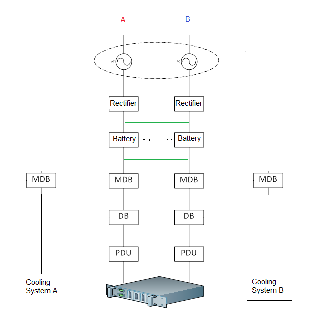
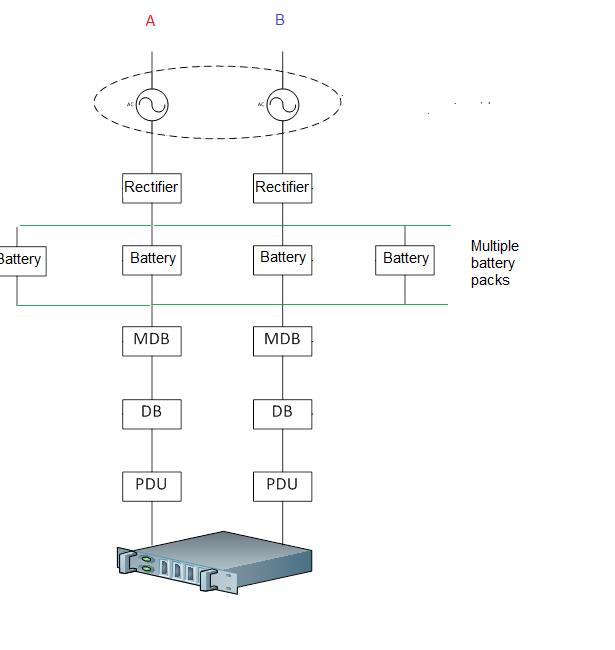
So, it seems to me that compromise is needed. We operate the DC load from solar panels during sunny days, and from other sources at night and cloudy days. In our DC-only data centre:

Solar distribution simple


(If we stick with traditional AC PSUs, in the above and subsequent diagrams, remove the rectifier and put a DC-AC invertor in the PV line.)

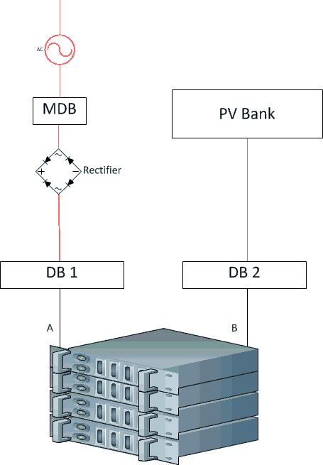
Unfortunately, this is too simple to work. At the start and end of the day, when the power available from solar cells is rapidly increasing or decreasing, even a single computer would have difficulty working out which supply to choose. This is because, unlike gen sets, which go from no power to flat-out almost instantaneously, solar panels energise in the same way that cups of water fill up. The power required by a computer is fixed, so a solar panel is useless to that computer until the panel is sufficiently energised to deliver all of the required power. If, for example, a single computer needs 350W, there’s no point in sticking 250W in the back: the computer won’t work. So we need to wait until the solar panel is fully energised before we can use it.

Solar compsumption 

This means that all the power we could be using in the post-dawn and pre-dusk times goes to waste. In addition, on cloudy or rainy days, the panels may never become fully energised.

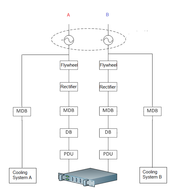
There’s a solution to this, which is called a DC combiner. This takes whatever power is available from the solar panels, and combines it with power from other sources. The resultant topology is something like this:

Solar distribution combiner


So each of the power rails combines power from conventional sources with solar power, and feeds that into the computers.

Unfortunately, the technology inside DC combiners has been patented (by Google amongst others – it’s nice to see my thoughts on DC are in good company). In an ideal world, owners of these patents would open source their DC combiners and we could take whatever we could get from the panels and make up the rest from other power sources.

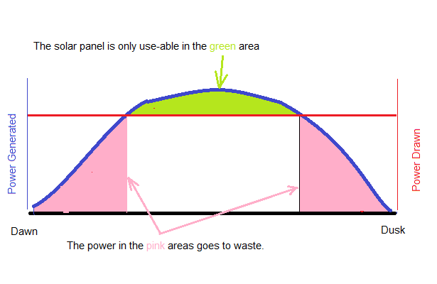
In this non-ideal world, there remains a compromise. Each time the solar panels deliver a threshold amount of power, we use it, and each time they fall below, we switch back. As a graph over the course of a day:

Solar compsumptoin

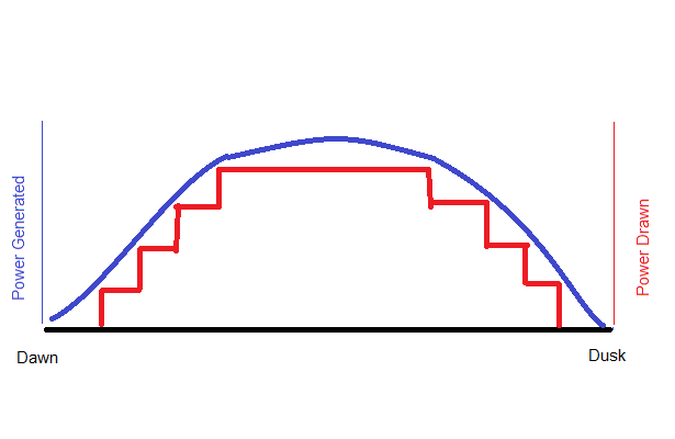
The smooth blue line is the total amount of power the panels generate. In and ideal (Google) world, we would draw the lot but, in our non-ideal world, we divide the DC load into evenly sized lumps – say 300kW / lump, and switch it over to solar power as and when the solar farm becomes sufficiently energised to power that lump. When the farm starts de-energising, we switch it back. On cloudy days, perhaps only 75% of the computers are solar-powered; at nights, 0% are.

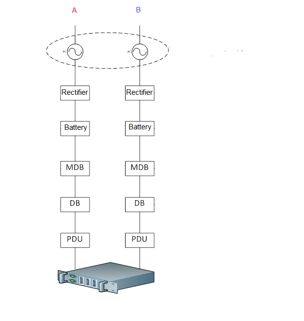
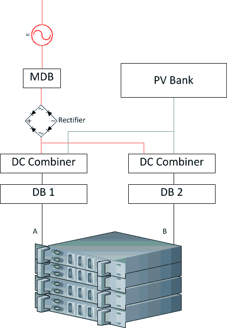
The topology to support this is:

Solar distribution

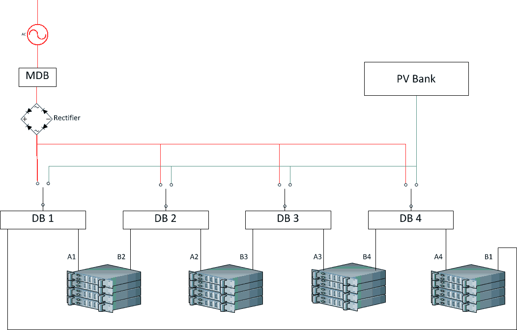
At the bottom, I’ve divided the IT load into four evenly balanced units. As one of the sizes in which off-the-shelf distribution panels come is 300kW, let’s say that each lump of IT load draws 300kW for a total of 1.2MW.

The AC power source at the top left includes gen sets, utility power and whatever: i.e. a reliable source of AC. I haven’t expanded this as I don’t want to clutter the diagram. The AC is converted, probably by multiple redundant rectifiers, into a reliable source of DC. This reliable source is distributed to four DBs, one for each lump of IT load.

At night, all IT loads run off conventional power. As the day starts, we wait until the panels are generating 25%, or 300kW, and switch the first load over. When the panels are up to 50%, we switch the second load over and so on – and in reverse at the end of the day. If it’s cloudy, we may never switch over all four loads and, if it’s really cloudy, we have to run off conventional power all day.

There would have to be a margin of error at the switch-to and switch-from points – for a 300kW IT load, perhaps we don’t switch to solar until we have at least 350kW spare, and we switch from solar if there is less than 325kW spare.

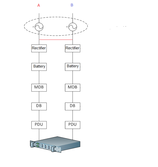
I’ve chosen four IT loads to keep the diagram simple. In practice, the size of the DBs would determine the number of IT loads and increment. As a flourish, I’ve also included full redundant paths just to show that this approach can yield them. And, yes, if it’s a conventional data centre with PSUs in the computers, scrub the rectifier, put an invertor (DC-AC convertor) after the solar panels, and everything will still work.

Cooling

Another possibility with solar panels is to forget about the IT, and use the panels to top up the power available to the cooling system, which will work much harder during the day. To do this, we put an invertor after the solar power to turn DC to AC. Combining two AC sources is straightforward as long as they are in-phase, and the invertors can deliver in-phase AC.

Follow-the-Clock Cloud Computing

A more radical solution – especially for cloud providers – is this: don’t run the data centre at all when it’s dark. Power the whole thing down and do the computing in the next time zone to the east in the morning and the west in the evening. This is especially viable for computing used by people (you know, human beings, on their phones and PCs), as (a) most people in TZ are asleep for the first few hours of daylight, so the cloud can compute for people to the east, and the converse at the end of the day.

*  *  *

This the best I can do on photovoltaic panels. The real problem with photovoltaic solar panels is that the sun doesn’t shine at night, and is diminished on cloudy days, so we either need to design around that, or we store electricity. As soon as we have to store electricity, we fight physics. The next post will look at a way around that.

Previous  Next

My Perfect Green Data Centre (7) – Power

Up to this point, I’ve looked at how data centres use power, and made a few suggestions on how reducing that power usage would reduce a data centre’s green footprint. As it happens nearly all of these changes reduce both capital and operational costs, so there’s a self-interest in being green.

It’s now time to look at the side where compromises are unavoidable: the sources of a data centre’s power. After all, if we go to all this trouble only for some smoke-belching power station to cover the surroundings in soot as it broils our planet, it’s in vain.

There is also the argument that data centres are not in the business of producing power. This is nonsense – your data wouldn’t have gen sets and batteries if data centres were not in that business, and the UI standard states that the on-site power is, from a design perspective, the primary power. Utility power is an option to save money; there are two UI-certified Tier-3 data centres that have are fully autonomous in power, with no connection to the grid.

And in South East Asia, there are cities of hundreds of thousands of people that consume less power than a single, medium-sized data centre. We have as much responsibility for the power we use as they (which is a lot).

So let’s rule:

  • Coal: Oh dear.
  • “Clean coal”: This is a myth. Coal consists of carbon, and burning anything amounts to mixing it with oxygen. Carbon + oxygen = carbon dioxide (or, to those who did chemistry at school, C+O2 = CO2). All coal is dirty.
  • Oil: Need I say anything?
  • LPG: Less bad, but less CO2 isn’t the same as no CO2.
  • Hydro: Although hydro doesn’t produce greenhouse gases as such, flooding large valleys full of rain forest has an impact, and those valleys are often cleared of their inhabitants with little regards for those inhabitants’ well-being. Plus, the carbon used in constructing these dams is not insignificant. So hydro is the probably the least bad conventional generation technology, and the least green of the renewables.
  • Wind: The closer one is to the poles (as in North and South), the better wind works. I’m concerned with data centres in the Tropics – with a capital T to indicate the area of the Earth between the Tropics of Cancer and Capricorn – and, in this part of the world, except when there’s a typhoon or hurricane, winds tend to be light. As a result, wind power isn’t effective.
  • Geo-thermal: This is great where the Earth’s mantle is thin, but building a data centre in such areas has independent disadvantages (such as being submerged in lava).
  • Bio-mass: This amounts to burning stuff, and there are two main variants. The first is the use of crops in general, and corn/maize in particular, which produces lots of CO2 and starves people; the second is to burn rubbish. Overall, I regard this technology as being “green” rather than green, but I’d like to hear if I’m wrong.

That leaves us with solar, and the next two posts will focus on the engineering possibilities with solar. In this one, I’ll say a few words about off-setting.

The idea of off-setting is that data centres tend to be near to urban areas where land is expensive, but solar farms need a lot of land, so are only economic if they’re built far from urban areas where land is cheap. What a green data centre owner does, therefore, is to build a solar farm which generates enough power for his data centre – say 5MW - in some rural area and feed that into the grid. The data centre draws a like amount from the grid. Although the power the data centre consumes is a mixture of dirty and clean, at least the net effect is zero.

This is a neat solution, but it faces a major hurdle in that many grids are unwilling or unable to purchase power on economically viable terms. The key issue is what’s known as the Feed-in Tariff, and the problem is that governments aren’t always very good at pricing the FITs.

A related problem is that most data centre operators want to invest in data centres, not solar farms, so need to find a partner to build the solar farm for them.

My issue with off-setting is that it doesn’t go the heart of the problem; it’s more of an out-of-sight-out-of mind approach. The data centre is still consuming dirty power, and building a nice solar farm a few hundred miles away has the feel of an accounting trick. So, in the next couple of posts, I’ll look at two possibilities for on-site generation.

Previous  Next

My Perfect Green Data Centre (6) – Pause for Breath

What was supposed to be one or two posts on DC became four, and what was supposed to be a single post on AC became three. It’s time to pause and consider.

The main idea so far is on the DC side of things. Supply computers with the DC they need rather than the AC which is convenient for us to provide, and three big impacts arise:

  1. The need for invertors (DC-AC convertors) and PSUs (AC-DC convertors) is eliminated. Manufacturing, shipping and destroying these components has a big carbon impact.
  2. A major source of 0ver-capacity is removed, thus allowing for leaner designs. A leaner design will be less wasteful, and less waste is always a good thing and nearly always green.
  3. Those data centres that use batteries need far fewer batteries, again with a big carbon impact.

On the AC side of things, the main load is cooling. All resources expended on cooling basically go up in smoke, so the more efficient cooling is, the better. Cooling is well-understood, but there is much more that data centres could do in terms of little things. Add all of these little things up and, although it may only be one percent here and a couple there, the cumulative effect would be to consume far less electricity.

The flip side is that, if we are to consolidate huge DC power supplies as the primary power source for IT, but stick with AC supplies for cooling, we may end up with a more complex design.


Power chain summary


(I’ve included A and B cooling systems to show how a Tier-4 or some Tier-3 configurations may, though need not necessarily look. For Tier-2, remove either cooling system and locate the redundancy within the system.)

Or, if we simply get rid of batteries and use flywheel or DRUPS:

Power chain summary flywheel

This may not look very different from a conventional topology, but with 70% of the power now in the DC side, it is very different. It also brings to mind a separate, though related point: how clean is the power that comes in at the top? The next few posts will look therefore look at clean power in general. After those, I’ll try and put all the pieces together.

Previous  Next

My Perfect Green Data Centre (4) – DC, Joining Rails

A further brief thought on the virtues of DC.

Remember this diagram?


Power chain batteries and rectifier

One legitimate question is why there are two PSUs in the typical server. Part of the answer is that PSUs break down: the internal fans break, the electronics get broken by power surges, broken power cables and the like. Eliminating PSUs also eliminates a source of unreliability. Without the PSUs, the only things going into the back are the live and neutral wires of a +12V DC power supply. The other answer is we have two PSUs because, at least in a Tier-3 or -4 data centre, it is sometimes necessary to shut down either the A or the B power supply, either for maintenance or for re-configuration.

For the latter reason, there is a certain degree of sense in delivering two separate wires to the server. But with DC, we have a lot more freedom about what happens between the power source and the server. AC delivers the power in a sine wave. If you join two AC supplies, their respective sine waves must be synchronized: if they’re not, you’ll get a James Bond result of sparks and pyrotechnics. But, if you join two DC supplies of the same voltage, nothing goes wrong. And this enables a further saving.

If we do this:

Power chain batteries and rectifier AC join

that red line will quite probably be red in reality. But if we do this:

Power chain batteries and rectifier DC join


The green line will be fine.

What does this buy us?

It buys us a much smaller battery pack. Battery life is measured in kilowatt hours, so a battery that can supply a kilowatt for one hour will have a 1 kW hr life, but so will a battery that can supply 10 kilowatts for six minutes.

A typical data centre will allow about 10 minutes of battery life. If this is based on a 1 MW load, that’s 166kW hours which, at a little over 2 kW hours per battery, is 800 batteries. But in the first drawing above, we need two complete battery packs, one on A and one on B, so a total of 1,600 batteries.

Using the topology with the green line, connecting the DC before the batteries (and possibly after them, too), means that we can combine these two battery packs.

Now, it won’t be quite that simple. We still need some redundancy in order that we can take complete sets of batteries off-line to replace or service them (lead-acid batteries are supposed to be topped up with water, and individual batteries should be inspected or monitored). But if we break our 800 battery requirement into 8 packs of 100 batteries each, and add a pack for redundancy, we’ve saved 700 batteries.

Power chain batteries and rectifier DC join multiple battery packs

As batteries last maybe 3 years, and a data centre lasts 20 years, that’s over 4,000 batteries over the life of the data centre. That’s a lot of green, space saved, cabling and wires saved. And all for giving the computers the power they need rather than the power we have.

Previous  Next


My Perfect Green Data Centre (5) – AC

In the last couple of posts, I’ve looked at the design of the power supply for the IT side of things and have argued that we should supply the computers directly with DC. In an ideal world, I could stop there: the power in a data centre would be for the almost exclusive use of IT, and everything else would be structure, security, and bits and pieces. But, we don’t live in an ideal world, and one way in which it fails to measure up to that standard is heat.

From an engineering point of view, computers are equivalent to electric toasters: they turn electricity into heat. Consequently, a large component of any data center is expelling that heat. Worse yet, if the air coming into computers is not cool enough, the computers will be damaged. Most computers are designed to the ASHREA A3 standard:

  • Temperature: 18-27C
  • Temperature Stability 5C/hr
  • Upper moisture limit 60% RH and 15C Dew Point
  • Lower moisture 5.5C

There are many parts of the world where this describes the climate, so there is therefore something to be said for Switch‘s approach to keeping within these limits. Switch put their data centre campuses in Reno and Las Vegas, Nevada, where the ambient conditions fall within these limits for nearly all of the year. Open the doors, blow the cool outside air in, have a few big fans to extract the heat, and your computers are operating within limits.

Unfortunately, at least 50% of the world’s population lives in South, South East and East Asia, and although it would be possible to put all the world’s data centres in places with cool climates and connect over fibre, the delays introduced by network latency would be problematic for real-time computing, and the costs of building those networks is high. In addition, many of countries have a legal requirement that data be held within country. So the reality is that most data is going to be in the same country as the consumer.

In nearly all of South and South-East Asia, the ambient conditions are way outside the ASHREA limits. We not only have to move large quantities of hot air generated by computers out of the data centre, we also have to cool and de-humidify the air coming in. That’s going to take a lot of energy.

Irrespective of the technology – chilled water for big data centres and DX for small ones are the most common - cooling requires some combination of compressors, pumps and fans. At the heart of all these is the electric motor. As the physics of the matter are such that DC electric motors are much less efficient that AC electric motors, we need an AC supply. As gen sets and grid power are AC, this leads to a very simple arrangement:


There seems little scope for simplification. But here’s on radical thought.

Generator sets consist of an engine, and electrical plants of a turbine, connected to an alternator. The alternator converts rotary kinetic energy to electrical energy. The motors at the heart of each compressor, pump and fan convert electricity to rotary kinetic motion. So one approach is to cut out the middle man and install a system of drive shafts and gear boxes that drives those compressors, pumps and fans directly.

I don’t know how to do the numbers for this, but I strongly suspect that whatever we gain by a self-cancelling two-fold conversion of energy, we lose in the inefficiencies of drive shafts and gear boxes. We also add multiple points of failure – and mechanical things fail much more often that solid-state devices – and a maintenance nightmare.

But here’s another possibility. Large car factories have a huge compressed air plant, and that air is piped to the individual robots. The robots themselves are operated by switching on and off the supply of air at the joints. Similarly, a data center could have a single source of compressed air that is piped to the compressors, fans and what-not.

I don’t have the knowledge to develop that thought, so I’ll stick with conventional cooling technologies (and welcome thoughts from people who do have the knowledge to develop that thought).

Previous  Next

My Perfect Green Data Centre (5) – Evaporative Cooling

I started thinking about this subject five years ago and, back then, I wondered if evaporative cooling would be useful in the humid tropics.

The form of evaporative cooling with which us humans are best associated is sweat. The reason sweat cools us down is not that we are covered in water, but that the water, when it evaporates, cools us.

In the dry air of Europe and North America, humidity is generally low, so evaporative cooling has not taken off. As it would seem that most HVAC engineers are educated in this tradition, whenever I mentioned evaporative cooling, I was steered quickly away. Even Dr. Hot, a consultant in thermodynamics, rubbished the idea. As he was the expert, I parked evaporative cooling in my bag of good-ideas-that-turned-out-to-be-rubbish.

Dr. Hot was dead wrong: so much for experts. A month ago I went to a data center fair in Hong Kong and came across Munters, a company that makes industrial-scale evaporative cooling for data centers. While I accept a certain amount of hype, their cooling system is the choice at Supernap’s new Tier-4 data centre in Thailand, and Munters claim that it saves so much power that, even in the tropics, a PUE of 1.2 is achievable – a massive saving on energy.

On the back of an envelope

IT Load PUE Cooling Power
2,500,000 2.0 2,500,000
2,500,000 1.7 1,750,000
2,500,000 1.3 750,000

So, the difference between a PUE of 1.7 and 1.3 is a 1MW generator set. A huge saving in capital cost (being green pays!), but also a significant reduction in the pollution that gen sets spew into the atmosphere, and the environmental impact of building, shipping and ultimately destroying the things.

That’s already good in a colo environment. In the self-contained pod that I sketched in my previous post, the idea would be to make the outer casing the evaporative cooler. Munter’s design re-circulates the air inside, so the idea would be to put the heat exchange on the wall, and the fans and pumps on the roof. Probably a rather expensive experiment, but I can’t help wondering if that may get the PUE down as far as it can go.

Previous Next

My Perfect Green Data Centre (4) – DC, Postscript 2

Here’s another advantage to delivering DC to the back of the computer: overcapacity.

A couple of years ago, I moved a client’s IT estate from its in-house server rooms to a colo operator. The in-house server rooms were not separately metered and the client had large call centers, so overall high electricity consumption. There was no way of establishing the power consumption, but the colo operator needed to know how much power to reserve for the base load. In the end, I got hold of some spec sheets for “typical servers” in their estate and made an educated guess of 2kW / rack. I always specify power-consumption be monitored at the rack level, so when we’d moved them in, I added up the numbers. The core switches, which came with 3kW PSUs, were pulling 1.2kW for the entire rack; the single biggest consumer was just over 4kW. The average was 1.3kW – I’d oversized by 30%.

When an engineer specifies a PSU for a computer, he does so based on maxima: the maximum number of processors, disks, RAM, etc. He then allows a safety margin. PSUs are manufactured in standard sizes, so he chooses the next standard size up. (HP’s tool is here.) He also assumes that the computer will run flat-out. Put all this together, and a computer that ticks over on 200W for most of its life will have a 500W PSU. Yet data centers are obliged to design a supply that can deliver this peak theoretical load. What we end up designing for is the sum of the maxima, rounded up.

If we deliver DC direct to the computers, we can eliminate the over-capacity due to (a) the rounding up and (b) using a sum when an average would suffice.

These can add up to big numbers. A server that requires 330W ends up with a 500W supply, and the data center provider ends up sizing for the 500W, not the 330W. Add that up across 5,000 servers, and we’re overdesigning by 850kW just because we’re rounding up.

The difference between the average peak demand and total peak demand is more difficult to put a number to, but the idea is that not every computer is going to run flat-out at the same time. At any given time, some computers will be running flat-out consuming all 330W, many will be rumbling along at, say, 200W, and a few will be fast asleep at basically 0W. If I assume a (slightly skewed) normal distribution, we end up with the difference between 5,000*330W and 5,000*200W = 650kW.

Add these two numbers together, and based on the 5,000*500W that we started with, and we have the difference between 2.5MW and 1MW. Yes, that’s a 60% reduction in the power we design for. And it’s not only the electricity supply, but the cooling too ends up over-sized. This all has a carbon footprint: we’re buying batteries, invertors, flywheels, gen sets, cooling, the whole lot, that will never be used.

Of course, in the real world we’d have to allow for various other factors, and we’d need actual data. But the point remains that by centralizing our PSUs into a couple of industrial-scale PSUs and distributing DC, we can come up with a much leaner design.

Previous  Next