Posts Tagged : Design

My Perfect Green Data Centre (9) – The Perfect Green Data Centre

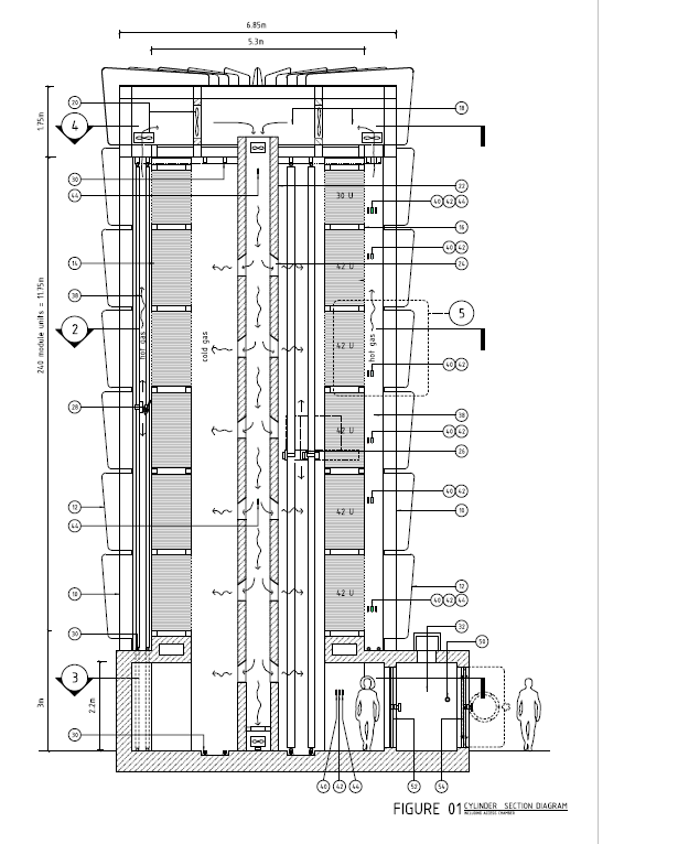
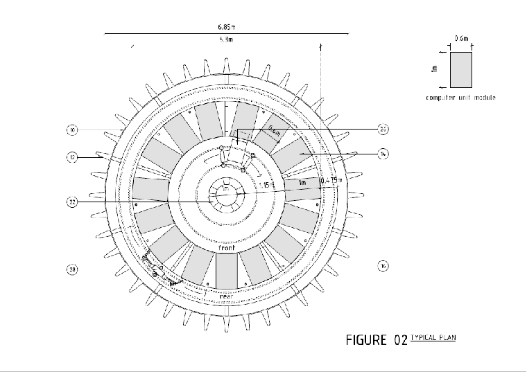
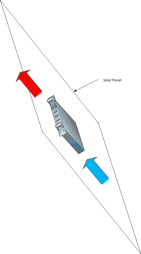
In this series, I’ve tried to unload everything that I see as being wrong about the way we think about, design and build data centres. I’ve said that my perfect green data centre is not a data centre at all, but consists of solar panels, with computers mounted on them, installed on people’s roofs. A second-best is the ultimate air containment monocoque. And, as the least good, a bodge job for colocation.

But, at a higher level, nothing I’ve said addresses the fundamental problem, which is that computers turn electricity into heat.

To some extent this will always be the case, but it needn’t be the case to the extent that it is. Nearly all servers use NMOS chips, and NMOS chews power. There’s nothing to be done about this. The basic unit of all digital technology is the transistor. NMOS requires a transistor and a resistor to create the most basic logical circuit (an invertor), and more complex functions similarly require resistors. Resistors dissipate unwanted electricity by turning it into heat. So NMOS chips necessarily turn electricity into heat.

But the computer chips that power your phone are not NMOS – and your phone battery would last minutes rather than hours, and your phone would burn a hole in your pocket if they were. The chips in your phone are CMOS. And CMOS consumes an order of magnitude less power.

This is because CMOS chips use almost no resistors. For every one transistor / resistor pair in NMOS, there will be two transistors in CMOS. Those transistors only use power at the instant a state changes, whereas resistors use power nearly half the time. (In an NMOS invertor, whenever the input is 1 and the output is 0, the resistor is active. Assuming on average that the invertor will spend equal amounts of time in both states, and the resistor’s pumping out heat half the time. In a CMOS invertor, one transistor is on and the other is off, and neither dissipates heat, so the average amount of power pumped out is close to zero. Similar cases apply to more complex functions.)

As transistors take up more space than resistors, and are more complex, CMOS packs fewer logical functions into more space. Because the construction is more complex, the yield – the proportion of correctly functioning chips coming off the production line – is lower, so CMOS are more expensive. But the power consumption is much, much lower.

Conversely, NMOS chips pack more computing into less space, and are less costly than CMOS chips of the same die size. Hence their ubiquity, especially in server grade equipment. The downside is that resistors turn electricity into heat and transistors don’t, so NMOS chips emit a great deal more power.

But the limiting factor in solar power is the insolation: the amount of solar energy that reaches the ground. This, for any given part of the world on any given day is fixed. Even if we recover 100% of that solar energy – and we never will – the 1,350W per square meter that comes from the sun in the tropics will power at most two or three off-the-shelf commodity NMOS servers. Those two or three servers will occupy much less than a square meter.

But that same 1,350W will power maybe a dozen CMOS servers. And the resultant extra density more than compensates for the fact that CMOS chips tend to be less powerful than NMOS chips.

In other words, there’s an imbalance. NMOS consumes solar energy faster than we can generate it; CMOS uses solar energy at roughly the same rate per square meter that we can generate it. And because we’re using that energy to power state changes – which is what matters - rather than to preserve states – which shouldn’t take any energy at all - we pack in far more computing into each square meter than we can with NMOS.

So the perfect green data centre consists of PV panels on people’s roofs, with CMOS servers attached, connected by wifi towers or fibre as appropriate, and with data replicated at time zones +8 and -8 hours away (or +120 and -120 degrees of longitude) so that computing follows the clock.

Or, in other words, the perfect green data centre consists of our planet Earth itself, shorn of the ugly concrete boxes that turn electricity into heat. Who’s up for building it? I’d be delighted to hear from you – chris,maden [at] cpmc.com.hk.

Previous

My Perfect Green Data Centre (8) – Colocation: The Best I Can Do

I’ve seen some amazing items of equipment in colocation data centres. The winner has to a drum printer, but I’ve seen passive 4-way hubs, any number of free-standing modems, more desktops than I care to remember, and that’s before we get to the tape drives, optical jukeboxes and voice recording equipment. And that’s only the digital stuff. The analogue equipment for telephony comes in shapes and sizes of which Heath Robinson would be proud.

So, although pre-mounting stuff in trays and having robots insert those trays into a sealed monocoque of the type I suggested in the last post may work 90% of the time, the 10% will kill any attempt at robotics. The range of things that goes into a colocation data centre is just to vast for anything but the current row and aisle, human-access data centre. Having untrained IT guys clambering around a vertical chamber, laden with heavy and expensive equipment, is a non-starter.

As to robots, forget it. They’re too expensive to be cost effective. And human incursion is binary: one either designs for it or doesn’t. If there are likely to be even a few of incursions a year, one must design for it, and one reaps the costs of both the robots and the infrastructure needed to deal with humans.

So what is there to do? Quite a lot. They’re all little things, and most of them have to do not so much with the engineering, but with the dynamics of how colocation providers interact with their clients.

On the engineering, insulate your building, deploy geothermal piling, install hot or cold aisle containment, use evaporative cooling, but also, look at the load. It is much more energy efficient to cool three 4kW racks than to cool a single 10kW and two 1kW racks, yet clients arrange their IT in the latter way all the time. Put intelligent PDUs on each and every rack, monitor the heck out the whole white space with temperature sensors, and re-arrange your client’s equipment to balance the temperature. Yes, there are constraints on cable length and demands of proximity, but even within these, the equipment layout can be optimized.

To do this, the contracts need to be restructured to reward the clients for good behaviour. Most colocation contracts I’ve seen (and I’ve seen many) rather than rewarding the client for good behaviour, reward the data centre operator for their colocation clients’ bad behaviour. It does not have to be this way. Colo providers sell space, electricity, network bandwidth and time. Break the electrical component down into base IT load (which is fixed) and cooling (which can almost always be reduced), and you incentivise the client to work with you to reduce his heat load.

Don’t allow your clients to use cages. I’ve mapped out the topology of enough networks by looking at the backs of racks to know that it can be done – but I had keys so didn’t have to peer through the grate. But the bigger points are that all IT estates consist of the same stuff – servers, storage and network - and unless you know what the hardware does and what the IP addresses are (yes, they’re supposed to be labeled…) knowing that the estate consists of servers, storage and networks is like knowing that a building consists of bricks, wood and metal. Furthermore, with virtualization technologies, the hardware is so abstracted from the network topology as to be almost irrelevant. So the cages serve almost no useful purpose in securing the estate. Yet cages are terrible for data centres: they screw up the airflow, stressing the cooling system. If anything, they offer a false sense of security: the real threat’s at the end of the wire, not some guy photographing your racks..

And anyway, cold air containment systems provide most of the perceived security advantages of cages.

And then there’s the Network and Security Operations Centres. Here’s the next generation NOC/SOC:

Phone

I’m not advertising or advocating the Huawei 9 Mate – the picture’s just to make the point: the technology is already available to monitor all systems and alert people when unexpected things happen. It can tell if a human is in the white space, check that against whether or not there should be a human in the white space, and which part of the white space that human should be in. SNMP is hardly new and any half-decent DCIM will send text messages, e-mails and the like if it thinks a component is breaking. All those flashy monitors and screens in the NOC and SOC serve no useful engineering purpose.

And then there are the little things. Use LED lighting, not fluorescent tubes, and switch the lights off it they’re not needed. Stay away from CFCs if you have DX units. If you’re using evaporative cooling, there’s no chilled water so no need for a raised floor – so don’t install one. I think that there’s no need for any permanent staff in a data centre but, if you must have people there hard at it doing nothing most of the time, give them LED lighting, efficient air-con, too.

Plant a few trees.

And finally, source clean power. If you must offset, offset, but at least put a solar panel on the roof. If nothing else, it can keep the staff cool and in light.

Previous  Next

My Perfect Green Data Centre (8) – A Robotic Cloud Data Centre

Having concluded in the previous post that the best data centre is no data centre, in this and the next post I’ll go for the second-best options for a cloud service and colocation data centres.

The reason I distinguish between cloud and colocation is that the IT in a cloud data centre is much more homogenous than that in a colo data centre. Where colocation tenants tend to pack their racks with all manner of stuff, cloud operators and internet service providers tend to buy thousands of identical of identical servers with identical disks, and identical network equipment. This opens possibilities.

The first is to keep humans out. Humans bring in dust, heat, moisture and clumsiness. We present a security risk. And we add a lot less to computing than we like to think.

If we are to keep humans out, what happens when things break? A simple answer, and one that I suspect will be the most cost-effective over the life-span of a cloud data centre, is “nothing.” Given the low cost of computer power, fixing a single broken server, disk or motherboard is hardly going to make a difference. That computer manufacturers no longer even quote the Mean Time Between Failures, a measure that determines the reliability of mechanical things, suggests that out of, say, 5,000 servers, 4,999 will be working just fine after five years.

If, however, we are going to insist on fixing things, how about robots?

I was told five years ago when I first thought of robotics in data centres, that robots in data centres would never work. For a colocation data centre, I came to agree. The best we can do would be to build a pair of robotic hands that are remotely operated by a human. This would keep the dust, heat and moisture out, but instead of having a weak, clumsy human bouncing off the racks, we’d have a strong, clumsy robot. On top of that, for remote, robotic hands to work, they need to be tactile, and to this day, tactile robotics costs some serious money.

But my friend Mark Hailes had a suggestion: for a cloud data centre, mount all the equipment in a standard sized tray with two power inputs and two fibre ports. Rather than have a fully-fledged robot, use existing warehouse technology to insert and remove these trays into and from the racks. There could be standard sized boxes, 1U, 2U and 4U, to accommodate different servers.

My friend Richard Couzens then inspired a further refinement, which is to have a rotunda rather than aisles and rows. This minimises the distances the robots have to move, and therefore reduces the number of moving parts, which ought to improve the reliability of the whole.

Finally, with robots doing the work, there is no particular need to stop at 42U: the computers can be stacked high.

Put these together, and we get a very different layout from that of a conventional data centre:

Pod 1

Pod 2

If that looks familiar, it’s because it’s the same layout I suggested here to take advantage of natural convection currents. So here’s the whole story.

Before operations, the tower will be populated with racks which are designed to receive trays. The racks will be fully wired with power and data. Human beings (as a group of humans can work more quickly than a single robot) will fill up the trays with computers and the racks with trays. When everything’s been plugged in, the humans leave. The entire tower is then sealed, the dirty air pumped out, and clean air pumped in. The tower will use evaporative cooling; that will be switched on and the computers powered up.

We only supply DC power. There is no AC in the tower, and consequently no high voltages. The robot (which is more of a dumb waiter than a cyborg) can be powered using compressed air or DC motors – that’s something for a robotics guru.

The tower is designed to be run for many years without human incursion. If something in a tray breaks, the robot will retrieve the tray and deliver it to the airlock, where a person picks it up and takes it away for repair or disposal. People outside the data centre will pack computer equipment into trays, insert the trays into an airlock at the bottom of the tower, from whence a robot will pick the tray up, transport it to its final location, and insert it.

When it’s time to replace the entire estate, the tower is depowered and humans can empty it out and build a new estate.

The robot uses the central core of tower. All it has to do is move up, down, around in circles and backwards and forwards. These are simple operations but nonetheless, mechanical stuff can break and does require preventative maintenance. When not in use, the robot therefore docks in an area adjacent to the airlock, so it can be inspected without humans entering the tower. As a last resort, if the robot breaks when in motion, or if something at the back of the racks breaks, a human can get in, but must wear a suit and breathing apparatus. That may sound extreme, but the tower will be hot and windy.

It may also be filled with non-breathable gas. I’m told that helium has much better thermal qualities than natural air, and filling the tower with helium would not only keep humans out, but would also obviate the need for fire protection. The lights (LED lighting, of course) would be off unless there’s a need for them to be on, and a couple of moveable cameras can provide eyes for security and when things go wrong.

Each tower would be self-contained. Multiple towers could be built to increase capacity. Exactly how close they could be, I don’t know. But this is a design that achieves a very high density of computer power in a very small area: that makes it suitable for places where land is expensive.

Last but not least, in this most aesthetically-challenged of industries, these towers would look really cool. So: Google, Facebook, Microsoft: run with it!

Previous  Next

My Perfect Green Data Centre (8) – Solar Meta-Topology

So far I’ve discussed the topology and engineering within a data centre. In this post, I take a big step back to produce a blueprint for any global internet provider such that, by combining follow-the-clock computing with a much lower-density arrangement, we get to a much lower carbon footprint.

I will now unpack that in reverse order.

Let’s start at the IT load. In an early post, I stated the ASHRAE A3 standard recommended thermal guidelines, which I have since assumed. But that’s not the whole story. Getting holding of the ASHRAE standards has become rather difficult as, like everyone else, they’ve become selfish with the information and want people to pay. However, there’s the link here guided me to the paper Clarification to ASHRAE Thermal Guidelines, which I believe is in the public domain, and which shows the full picture: although 18-27C is the recommended operating range of temperatures and <60% the recommended humidity, the allowable range is 5-40C / <85% (and, for A4, 5-45C / < 90%). Ask my laptop: computers can work in high heat and humidity and, if they’re solid state, can last for many years. Put a motherboard built to ASHRAE A4 standard in the middle of a room in the tropics, aim a fan at it, and it will run almost indefinitely.

However, in a data centre, we don’t have a single motherboard in the middle of a room. We have many motherboards. This leads to lots of heat being generated in a relatively small area, and the problem of cooling in data centres is not caused by the computers per se, but rather by our insistence on packing lots of computers into a small space. The more we spread the computers out, the easier they become to cool. If we spread them out sufficiently, and if they’re built to withstand a high intake temperature, all we need to do is extract the hot output air.

The reason that we pack them in is that, in the past, it was held to be important that the computers were close to the people they served. This meant that data centres were built in or near urban areas where land is expensive, so the extra cost of an expensive cooling system was justified on the basis that computers could be packed.

But things have changed. From a security standpoint, the farther away the data centre is from urban areas, the better. From the point of view of land-cost, likewise. And it is now far cheaper to run fibre to a rural area than to buy land in an urban area.

Next, let’s take 1,350W/m2 insolation as a physical constraint. I suspect that we’ll never do much better than 50% recovery, so we can generate, say, 650W/m2. One of the problems I’ve been tackling in the last two posts has been that our load has a much higher density: if we’re stacking ten servers to a rack, then for every 0.6m2 rack we need 6m2 of solar panel. Allowing for the fact that the racks themselves are spread out, I concluded that every m2 of rack needs 2.5m2 of solar power (whether PV or CSP).

Here’s my proposal.

The power from a single panel, 650W, is enough to power a mid-range motherboard with a few disks. So, rather than having a huge array of panels over there powering a whole bunch of low- to medium-density computing over here, put the computing where the sun shines. Assuming the motherboard is built to ASHRAE A4, the problem is not intake temperature, but extracting the heat. To address this, we design the motherboard such that all the hot stuff is at the top, and we put a couple of fans at the bottom to blow the heat out. We protect the motherboard from rain by enclosing it (hopefully in some low-footprint material).

Panel with Computer

Okay, no prizes for the artwork. The rhomboid-ey thing is the solar panel, the computer’s strapped to the back, and the arrows indicate cool(ish) air coming in and hot air being blown out.

Or, perhaps, we have compute-panels and disk-panels, arranged in some repeating matrix:

comps and Disks


Each panel+motherboard is in principle self-contained. However – a problem for a mathematical topologist – panels should be interconnected in such a way that a cloud passing over doesn’t cause dead zone to zoom across the array. The entire array, and the weather, should be monitored so that, when it gets cloudy, selected computers can be de-powered depending on the extent of the darkness.

At night, instead of using batteries, de-power the entire solar-compute farm, and off-load the computing to the next solar-compute farm to the west. In the morning, computing will arrive from the sol-comp farm to the east.

Now let me push it further. In a world with starving people, it makes little sense to replace tracts of agricultural land with solar arrays when there are millions of small villages across the tropics that already have roofs. Put a few solar-compute panels on each roof, and interconnect them by sticking a wifi tower in the village. Pay the village or villagers not with rent, but by providing each house with a battery, some LED lights so that the children can study at nights, and an induction cooker so that villagers don’t cut down trees for firewood. Recruit a couple of villagers and put a NOC/SOC on their tablet to give them responsibility for their own village solar-compute array. Make this part of a training and recruitment program so that the NOC/SOC have a future that goes beyond installing the solar-compute panels and fixing them when they break.

If computing is going to follow the clock, sooner or later it’s going to fall into an ocean. Most oceans have land to the north or south, but the Pacific Ocean is a particularly large hop. In the north, it’s possible to string data centres along the west coast of North America and the east coast of Eurasia, and in the south, the Polynesian archipelago could keep the bits and bytes being crunched.

That covers the edges. For the ocean itself, with the oil industry in its death throes (what a shame they don’t use all that money and power to switch business models to renewables rather than sticking with the cook-the-planet model), quite a lot of large floating structures – oil rigs, supertankers and the like – will be available on the cheap. They could form a string of permanently moored data centres that run off some combination of wave, wind and solar power.

Does this sound more like science fiction than engineering? Perhaps. But nothing in the above is beyond the reach of today’s technology and engineering: we can design motherboards, chips and disks that run reliably in hot and humid places; PV technology is already almost there; the underlying control systems, network connectivity and ability to shunt data are also already there. What’s lacking is not the engineering or the technology, but the will. Google, Amazon, Facebook, where are you?

Not on this blog. So, in the next post, I’ll take all the bits and put them together in a more conventional, less frightening way,

Previous  Next

My Perfect Green Data Centre (7) – Concentrated Solar Power

In the previous post, I came to the sad conclusion that harnessing sunlight with PV panels is not feasible as a reliable, green power source for a 24/7 data centre. It is at best an auxiliary power source, or a boost to the primary source during daylight hours.

This is because nature is not very good at storing electricity. But nature is good at storing other types of energy, and is very good at storing heat. And this is where Concentrated Solar Power comes in. There’s a detailed wiki article here; the short story is that CSP uses multiple mirrors to reflect the sun’s heat to a small point. That point in turn heats up molten salts, which in turn super-heat water to drive a conventional steam turbine.

The downside is that where PV has a single conversion – a photon knocks an electron free – CSP has multiple conversions – from solar radiation to heat to kinetic motion which drives a turbine and finally, via induction in an alternator, to electricity. Hence, although each of these steps can be very efficient, the theoretical limit on efficiency is going to be lower. However, as even domestic solar water heaters are 70% efficient, we’re starting at a much higher baseline than PV.

The joy of this is that rather than battle nature by trying to store electricity, CSP opens the possibility of storing the heated molten salts in a tank for release during the dark hours of the night. Insulating a tank is much easier than persuading molecules to host itinerant electrons. And, as I keep saying, there’s more to greenness than efficiency. Building a tank to contain hot stuff requires far fewer nasty chemicals than batteries. In addition, the tank’s life time is more or less indefinite, whereas batteries die.

Given these tensions, the overall viability of CSP is still up in the air. Predicted efficiencies for CSP are below theoretical ones, and the costs are 2-3 times those of PV panels (albeit, PV panels without the battery packs). So this is a technology that’s still not quite ready for the big time. But because energy is stored as heat, CSP offers the promise of 24/7 solar power without the horrors of batteries.

The wiki article appears to be 2-3 years out of date. More up to date information is on the National Renewable Energy Laboratory website. This suggests another problem, which is that the power densities from CSP just aren’t in the same league as those from PV panels. The site has an index of projects here, and most CSP plants cover large areas.

And this comes back to the nature of solar radiation: even if we recover up to 60%-70% of insolated energy, and even if we find ways of storing solar energy overnight that are 80% efficient, we still need a rainy-day buffer. Put this altogether, and the 1,350W / m2 diminishes fast. 70%*80% = 56%. Add a rainy-day buffer of a day or two, and we’re down to 30%. That’s 400W / m2. A typical data centre will consume 4kW / rack. After allowing for the usual factors, each rack takes about 4-5 m2 of space, so say 1kW / m2. That means for every 1 m2 of IT load, we need 2.5m2 of solar capture. That’s a 2.5:1 ratio at best. In practice, it’s going to be much worse.

Hence we find ourselves on a trajectory back to off-setting.

But before we go there, perhaps we’re solving the wrong problem. And that’s for the next post,

Previous  Next

My Perfect Green Data Centre (7) – Photovoltaics

Back to engineering, but first a disclaimer. Whatever numbers I use in this post are wrong. Photovoltaic technology (solar panels) and battery technologies are evolving so rapidly that everything is out of date as soon as it hits the market. So although I believe myself to have got the concepts right, the calculations are intended to show the type of calculation involved, but probably over-estimate the downside and under-estimate the upside. Having said that, the numbers are not order-of-magnitude wrong. They may be 10% or 20% out, but probably not much more.

The advantages of using solar are obvious: sunlight is – at least until the oil companies get their hands on it – free. Photovoltaic (PV) panels generate DC, not AC, and most of our load is DC. That’s a single conversion from photons to DC electricity, rather than from coal (or whatever) to steam to rotational kinetic to AC (via induction in an alternator) to DC, which will be inherently more efficient.

First, the footprint. The carbon footprint of PV panels is poorly understood. All we can say is that the numerator in any calculation consists almost entirely of non-renewables, so will asymptote to infinity. However, PV panels have indefinite life spans, which makes for an equally big denominator. So, overall, the green footprint asymptotes to ∞/∞=1. This is much better than hydrocarbons, for which the numerator is infinite and the denominator – burn it once and it’s gone – is finite.

Second, space. The amount of power a PV panel can generate is the solar radiation multiplied by the efficiency of the panel. In the tropics, the solar radiation is about 1,350kW / m2. I’m not sure how efficient the latest generation is, but let’s say about 30% (a wiki article says 20% is nearer the mark, but the article seems last to have been updated in 2014). To generate 1MW of power, therefore, we need 1MW / (1,350W/m2*30%) = 2,469 m2 of space. A typical data centre budgets 4kW per rack, so 1 MW is 250 racks, and at 5m2 / rack including non-white space, that’s 1,250 m2: although we don’t get quite enough power from putting the panels on the roof, nor do we have to buy vast tracts more land to put the panels on. Cover the car park and we’re done.

So far, so good. But, as any climate denier is quick to point out, the sun doesn’t shine at nights. If we’re to keep our data centre running 24/7 we need batteries.

In a conventional data centre, the batteries are expected to provide power in the brief gap between the primary power dropping out and the secondary power kicking in. As a result, batteries provide power for maybe ten minutes per incident, and there’s a gap of hours, if not days or months between incidents. In normal circumstances the time it takes to recharge the batteries doesn’t matter.

This is just as well, because it takes longer to recharge batteries than to charge them. However, if we’re running of PV panels, the power drops out every night, and we need to have the batteries re-charged and ready to go in time for the next night.

There’s a handy paper here which describes the calculations for lead-acid batteries, and the data sheet for a typical industrial scale battery is here (I am not advocating or advertising this battery – it’s just the first one on Alibaba that had a full spec sheet). Here are the calculations:

PV batteries calc

This is an Excel file you can download and play with. The measure of how long it takes to recharge a battery is its efficiency, and the handy paper says that lead-acid batteries are typically 65% efficient. The spreadsheet calculates the number of batteries needed based on that. The result is 1,667 batteries per MW using the batteries in the data sheet.

These are industrial, not car batteries, and weigh 175 kg a piece. 1,667*175kg is 291 tons of lead-acid battery to keep the data centre running 24/7. Furthermore, these batteries last 10-12 years, so need to be replaced once in the life of the data centre, so that’s 582 tons – imagine 350 crushed cars. And that’s for 1MW. The average data centre is more like 10MW, so that’s 3,500 crushed cars. Quarrying, shipping and destroying 5,800 tons of lead, acid and PVC casing has a pretty significant carbon footprint. And although Lithium-ion cells are more efficient, they come at a higher carbon footprint because, where lead is commonplace, lithium is rare.

The other problem is that we need to buy enough PV panels not only to power the data centre, but also to charge the batteries. As the batteries are 65% efficient, that implies that for every Watt of power, we need an additional Watt/.65 for charging, so we need (1+1/.65) * 2,469 m2=6,267m2 of panel per MW. For 10MW, we are buying vast tracts more of land than we’d otherwise need.

And, after all of this, if there are few days in a row of heavy cloud and little sun, all of the batteries will be exhausted and all this in vain.

What this comes down to is a physical manifestation of the abstract physics I mentioned some time back, that electricity is electrons in motion, and that storing electrons when they’re not in motion but in such a way that they can quickly be, is difficult. As a result, whatever greenness we gain by using PV panels, we lose in terms of the huge footprint in manufacturing all the batteries and extra panels we need to keep the data centre light at night.

So, it seems to me that compromise is needed. We operate the DC load from solar panels during sunny days, and from other sources at night and cloudy days. In our DC-only data centre:

Solar distribution simple


(If we stick with traditional AC PSUs, in the above and subsequent diagrams, remove the rectifier and put a DC-AC invertor in the PV line.)

Unfortunately, this is too simple to work. At the start and end of the day, when the power available from solar cells is rapidly increasing or decreasing, even a single computer would have difficulty working out which supply to choose. This is because, unlike gen sets, which go from no power to flat-out almost instantaneously, solar panels energise in the same way that cups of water fill up. The power required by a computer is fixed, so a solar panel is useless to that computer until the panel is sufficiently energised to deliver all of the required power. If, for example, a single computer needs 350W, there’s no point in sticking 250W in the back: the computer won’t work. So we need to wait until the solar panel is fully energised before we can use it.

Solar compsumption 

This means that all the power we could be using in the post-dawn and pre-dusk times goes to waste. In addition, on cloudy or rainy days, the panels may never become fully energised.

There’s a solution to this, which is called a DC combiner. This takes whatever power is available from the solar panels, and combines it with power from other sources. The resultant topology is something like this:

Solar distribution combiner


So each of the power rails combines power from conventional sources with solar power, and feeds that into the computers.

Unfortunately, the technology inside DC combiners has been patented (by Google amongst others – it’s nice to see my thoughts on DC are in good company). In an ideal world, owners of these patents would open source their DC combiners and we could take whatever we could get from the panels and make up the rest from other power sources.

In this non-ideal world, there remains a compromise. Each time the solar panels deliver a threshold amount of power, we use it, and each time they fall below, we switch back. As a graph over the course of a day:

Solar compsumptoin

The smooth blue line is the total amount of power the panels generate. In and ideal (Google) world, we would draw the lot but, in our non-ideal world, we divide the DC load into evenly sized lumps – say 300kW / lump, and switch it over to solar power as and when the solar farm becomes sufficiently energised to power that lump. When the farm starts de-energising, we switch it back. On cloudy days, perhaps only 75% of the computers are solar-powered; at nights, 0% are.

The topology to support this is:

Solar distribution

At the bottom, I’ve divided the IT load into four evenly balanced units. As one of the sizes in which off-the-shelf distribution panels come is 300kW, let’s say that each lump of IT load draws 300kW for a total of 1.2MW.

The AC power source at the top left includes gen sets, utility power and whatever: i.e. a reliable source of AC. I haven’t expanded this as I don’t want to clutter the diagram. The AC is converted, probably by multiple redundant rectifiers, into a reliable source of DC. This reliable source is distributed to four DBs, one for each lump of IT load.

At night, all IT loads run off conventional power. As the day starts, we wait until the panels are generating 25%, or 300kW, and switch the first load over. When the panels are up to 50%, we switch the second load over and so on – and in reverse at the end of the day. If it’s cloudy, we may never switch over all four loads and, if it’s really cloudy, we have to run off conventional power all day.

There would have to be a margin of error at the switch-to and switch-from points – for a 300kW IT load, perhaps we don’t switch to solar until we have at least 350kW spare, and we switch from solar if there is less than 325kW spare.

I’ve chosen four IT loads to keep the diagram simple. In practice, the size of the DBs would determine the number of IT loads and increment. As a flourish, I’ve also included full redundant paths just to show that this approach can yield them. And, yes, if it’s a conventional data centre with PSUs in the computers, scrub the rectifier, put an invertor (DC-AC convertor) after the solar panels, and everything will still work.

Cooling

Another possibility with solar panels is to forget about the IT, and use the panels to top up the power available to the cooling system, which will work much harder during the day. To do this, we put an invertor after the solar power to turn DC to AC. Combining two AC sources is straightforward as long as they are in-phase, and the invertors can deliver in-phase AC.

Follow-the-Clock Cloud Computing

A more radical solution – especially for cloud providers – is this: don’t run the data centre at all when it’s dark. Power the whole thing down and do the computing in the next time zone to the east in the morning and the west in the evening. This is especially viable for computing used by people (you know, human beings, on their phones and PCs), as (a) most people in TZ are asleep for the first few hours of daylight, so the cloud can compute for people to the east, and the converse at the end of the day.

*  *  *

This the best I can do on photovoltaic panels. The real problem with photovoltaic solar panels is that the sun doesn’t shine at night, and is diminished on cloudy days, so we either need to design around that, or we store electricity. As soon as we have to store electricity, we fight physics. The next post will look at a way around that.

Previous  Next

My Perfect Green Data Centre (7) – Power

Up to this point, I’ve looked at how data centres use power, and made a few suggestions on how reducing that power usage would reduce a data centre’s green footprint. As it happens nearly all of these changes reduce both capital and operational costs, so there’s a self-interest in being green.

It’s now time to look at the side where compromises are unavoidable: the sources of a data centre’s power. After all, if we go to all this trouble only for some smoke-belching power station to cover the surroundings in soot as it broils our planet, it’s in vain.

There is also the argument that data centres are not in the business of producing power. This is nonsense – your data wouldn’t have gen sets and batteries if data centres were not in that business, and the UI standard states that the on-site power is, from a design perspective, the primary power. Utility power is an option to save money; there are two UI-certified Tier-3 data centres that have are fully autonomous in power, with no connection to the grid.

And in South East Asia, there are cities of hundreds of thousands of people that consume less power than a single, medium-sized data centre. We have as much responsibility for the power we use as they (which is a lot).

So let’s rule:

  • Coal: Oh dear.
  • “Clean coal”: This is a myth. Coal consists of carbon, and burning anything amounts to mixing it with oxygen. Carbon + oxygen = carbon dioxide (or, to those who did chemistry at school, C+O2 = CO2). All coal is dirty.
  • Oil: Need I say anything?
  • LPG: Less bad, but less CO2 isn’t the same as no CO2.
  • Hydro: Although hydro doesn’t produce greenhouse gases as such, flooding large valleys full of rain forest has an impact, and those valleys are often cleared of their inhabitants with little regards for those inhabitants’ well-being. Plus, the carbon used in constructing these dams is not insignificant. So hydro is the probably the least bad conventional generation technology, and the least green of the renewables.
  • Wind: The closer one is to the poles (as in North and South), the better wind works. I’m concerned with data centres in the Tropics – with a capital T to indicate the area of the Earth between the Tropics of Cancer and Capricorn – and, in this part of the world, except when there’s a typhoon or hurricane, winds tend to be light. As a result, wind power isn’t effective.
  • Geo-thermal: This is great where the Earth’s mantle is thin, but building a data centre in such areas has independent disadvantages (such as being submerged in lava).
  • Bio-mass: This amounts to burning stuff, and there are two main variants. The first is the use of crops in general, and corn/maize in particular, which produces lots of CO2 and starves people; the second is to burn rubbish. Overall, I regard this technology as being “green” rather than green, but I’d like to hear if I’m wrong.

That leaves us with solar, and the next two posts will focus on the engineering possibilities with solar. In this one, I’ll say a few words about off-setting.

The idea of off-setting is that data centres tend to be near to urban areas where land is expensive, but solar farms need a lot of land, so are only economic if they’re built far from urban areas where land is cheap. What a green data centre owner does, therefore, is to build a solar farm which generates enough power for his data centre – say 5MW - in some rural area and feed that into the grid. The data centre draws a like amount from the grid. Although the power the data centre consumes is a mixture of dirty and clean, at least the net effect is zero.

This is a neat solution, but it faces a major hurdle in that many grids are unwilling or unable to purchase power on economically viable terms. The key issue is what’s known as the Feed-in Tariff, and the problem is that governments aren’t always very good at pricing the FITs.

A related problem is that most data centre operators want to invest in data centres, not solar farms, so need to find a partner to build the solar farm for them.

My issue with off-setting is that it doesn’t go the heart of the problem; it’s more of an out-of-sight-out-of mind approach. The data centre is still consuming dirty power, and building a nice solar farm a few hundred miles away has the feel of an accounting trick. So, in the next couple of posts, I’ll look at two possibilities for on-site generation.

Previous  Next

My Perfect Green Data Centre (6) – Pause for Breath

What was supposed to be one or two posts on DC became four, and what was supposed to be a single post on AC became three. It’s time to pause and consider.

The main idea so far is on the DC side of things. Supply computers with the DC they need rather than the AC which is convenient for us to provide, and three big impacts arise:

  1. The need for invertors (DC-AC convertors) and PSUs (AC-DC convertors) is eliminated. Manufacturing, shipping and destroying these components has a big carbon impact.
  2. A major source of 0ver-capacity is removed, thus allowing for leaner designs. A leaner design will be less wasteful, and less waste is always a good thing and nearly always green.
  3. Those data centres that use batteries need far fewer batteries, again with a big carbon impact.

On the AC side of things, the main load is cooling. All resources expended on cooling basically go up in smoke, so the more efficient cooling is, the better. Cooling is well-understood, but there is much more that data centres could do in terms of little things. Add all of these little things up and, although it may only be one percent here and a couple there, the cumulative effect would be to consume far less electricity.

The flip side is that, if we are to consolidate huge DC power supplies as the primary power source for IT, but stick with AC supplies for cooling, we may end up with a more complex design.


Power chain summary


(I’ve included A and B cooling systems to show how a Tier-4 or some Tier-3 configurations may, though need not necessarily look. For Tier-2, remove either cooling system and locate the redundancy within the system.)

Or, if we simply get rid of batteries and use flywheel or DRUPS:

Power chain summary flywheel

This may not look very different from a conventional topology, but with 70% of the power now in the DC side, it is very different. It also brings to mind a separate, though related point: how clean is the power that comes in at the top? The next few posts will look therefore look at clean power in general. After those, I’ll try and put all the pieces together.

Previous  Next

My Perfect Green Data Centre (4) – DC, Joining Rails

A further brief thought on the virtues of DC.

Remember this diagram?


Power chain batteries and rectifier

One legitimate question is why there are two PSUs in the typical server. Part of the answer is that PSUs break down: the internal fans break, the electronics get broken by power surges, broken power cables and the like. Eliminating PSUs also eliminates a source of unreliability. Without the PSUs, the only things going into the back are the live and neutral wires of a +12V DC power supply. The other answer is we have two PSUs because, at least in a Tier-3 or -4 data centre, it is sometimes necessary to shut down either the A or the B power supply, either for maintenance or for re-configuration.

For the latter reason, there is a certain degree of sense in delivering two separate wires to the server. But with DC, we have a lot more freedom about what happens between the power source and the server. AC delivers the power in a sine wave. If you join two AC supplies, their respective sine waves must be synchronized: if they’re not, you’ll get a James Bond result of sparks and pyrotechnics. But, if you join two DC supplies of the same voltage, nothing goes wrong. And this enables a further saving.

If we do this:

Power chain batteries and rectifier AC join

that red line will quite probably be red in reality. But if we do this:

Power chain batteries and rectifier DC join


The green line will be fine.

What does this buy us?

It buys us a much smaller battery pack. Battery life is measured in kilowatt hours, so a battery that can supply a kilowatt for one hour will have a 1 kW hr life, but so will a battery that can supply 10 kilowatts for six minutes.

A typical data centre will allow about 10 minutes of battery life. If this is based on a 1 MW load, that’s 166kW hours which, at a little over 2 kW hours per battery, is 800 batteries. But in the first drawing above, we need two complete battery packs, one on A and one on B, so a total of 1,600 batteries.

Using the topology with the green line, connecting the DC before the batteries (and possibly after them, too), means that we can combine these two battery packs.

Now, it won’t be quite that simple. We still need some redundancy in order that we can take complete sets of batteries off-line to replace or service them (lead-acid batteries are supposed to be topped up with water, and individual batteries should be inspected or monitored). But if we break our 800 battery requirement into 8 packs of 100 batteries each, and add a pack for redundancy, we’ve saved 700 batteries.

Power chain batteries and rectifier DC join multiple battery packs

As batteries last maybe 3 years, and a data centre lasts 20 years, that’s over 4,000 batteries over the life of the data centre. That’s a lot of green, space saved, cabling and wires saved. And all for giving the computers the power they need rather than the power we have.

Previous  Next


My Perfect Green Data Centre (5) – AC

In the last couple of posts, I’ve looked at the design of the power supply for the IT side of things and have argued that we should supply the computers directly with DC. In an ideal world, I could stop there: the power in a data centre would be for the almost exclusive use of IT, and everything else would be structure, security, and bits and pieces. But, we don’t live in an ideal world, and one way in which it fails to measure up to that standard is heat.

From an engineering point of view, computers are equivalent to electric toasters: they turn electricity into heat. Consequently, a large component of any data center is expelling that heat. Worse yet, if the air coming into computers is not cool enough, the computers will be damaged. Most computers are designed to the ASHREA A3 standard:

  • Temperature: 18-27C
  • Temperature Stability 5C/hr
  • Upper moisture limit 60% RH and 15C Dew Point
  • Lower moisture 5.5C

There are many parts of the world where this describes the climate, so there is therefore something to be said for Switch‘s approach to keeping within these limits. Switch put their data centre campuses in Reno and Las Vegas, Nevada, where the ambient conditions fall within these limits for nearly all of the year. Open the doors, blow the cool outside air in, have a few big fans to extract the heat, and your computers are operating within limits.

Unfortunately, at least 50% of the world’s population lives in South, South East and East Asia, and although it would be possible to put all the world’s data centres in places with cool climates and connect over fibre, the delays introduced by network latency would be problematic for real-time computing, and the costs of building those networks is high. In addition, many of countries have a legal requirement that data be held within country. So the reality is that most data is going to be in the same country as the consumer.

In nearly all of South and South-East Asia, the ambient conditions are way outside the ASHREA limits. We not only have to move large quantities of hot air generated by computers out of the data centre, we also have to cool and de-humidify the air coming in. That’s going to take a lot of energy.

Irrespective of the technology – chilled water for big data centres and DX for small ones are the most common - cooling requires some combination of compressors, pumps and fans. At the heart of all these is the electric motor. As the physics of the matter are such that DC electric motors are much less efficient that AC electric motors, we need an AC supply. As gen sets and grid power are AC, this leads to a very simple arrangement:


There seems little scope for simplification. But here’s on radical thought.

Generator sets consist of an engine, and electrical plants of a turbine, connected to an alternator. The alternator converts rotary kinetic energy to electrical energy. The motors at the heart of each compressor, pump and fan convert electricity to rotary kinetic motion. So one approach is to cut out the middle man and install a system of drive shafts and gear boxes that drives those compressors, pumps and fans directly.

I don’t know how to do the numbers for this, but I strongly suspect that whatever we gain by a self-cancelling two-fold conversion of energy, we lose in the inefficiencies of drive shafts and gear boxes. We also add multiple points of failure – and mechanical things fail much more often that solid-state devices – and a maintenance nightmare.

But here’s another possibility. Large car factories have a huge compressed air plant, and that air is piped to the individual robots. The robots themselves are operated by switching on and off the supply of air at the joints. Similarly, a data center could have a single source of compressed air that is piped to the compressors, fans and what-not.

I don’t have the knowledge to develop that thought, so I’ll stick with conventional cooling technologies (and welcome thoughts from people who do have the knowledge to develop that thought).

Previous  Next